Coding this change box was really tricky only because I needed a persistent variable that could be written and accessed over multiple program runs.
Arduino has EEPROM memory which is writable and persistent, HOWEVER you can only store one byte of data at each EEPROM address.
I did a lot of research online and was playing around with some functions to splice and store data over several addresses when I found someone who had written the functions already.
----------
Full disclosure and Attribution:
I used the functions EEPROM_Write_Int and EEPROM_READ_Int
StackExchange Question: "How to Store 2 analogRead values and read using EEPROM for Arduino uno?"
Author: Anurag S. Vasanwala (AnuragVasanwala@gmail.com)
----------
I needed to change one thing in the write function:
It turns out that EEPROM has a limited number of writes before the address wears out. I changed the final EEPROM.write() to EEPROM.update(), because .update() will only rewrite if the data is different saving memory
This problem also meant that I had to flag each sense of a coin from the photo interruptors and only update my EEPROM within a flagged if statement. If one ended up outside of an if statement I could burn through the address very quickly because of how many cycles the program can go through every second.
I then just printed the total on the LCD screen in my void loop() so that it updates in real time
The reset button simply saves zero to all the EEPROM addresses
I wanted to laser cut my housing so I built an Illustrator file that had appropriate tongue and groove walls for easy assembly
I also include raster etching for the lettering and detail work of the different coins
After I managed to get the laser cuts done I simply had to glue all the sides together expect the top (which I wanted to put on hinges so that you could access the coins/circuit inside.
I ended up going for the non linear slot position so that vessels could be placed under each slot catching the different denominations of coins separately.
The etching turned out great!
Sound = Glass!
I tried various materials for the interaction design component of dropping in the coins, especially with sound.
It turns out glass mason jars make a beautiful *cha chingsound so I have three small mason jars corresponding to the different slots
The Circuit:
Wiring the circuit turned out to be quite complicated, basically it went:
LCD has 6 pin connections one of which is a potentiometer to control brightness of the backlight
it also has 2 power pins and three ground pins
I ended up soldering it all together so that it could fit in the limited number of available powers/grounds/pins on the Arduino
Each Photo interrupter needed:
A power and ground on one side
A power and analog pin on the other side with a pull-down resistor to ground.
Depending on how much resistance you put across the emitter the reading varies
I also needed a reset button which was a basic button circuit to a digital pin
Finally I spliced a switch into my battery power supply to power the whole thing
This is to log the total amount of money in my change box
3x Photo Interrupter:
These will log the amount of money put into the box
Each sensor will map to a certain coin / value
With each interruption the coin value is added to the total in Arduino memory
Things that are still needed:
I need a simple on / off switch to turn on the system and LCD screen
I need some mechanism of resetting the memory - maybe a button inside the box that you hold to reset.
Design:
I am working with the size of the Arduino plus the breadboard. What I'm thinking is forego the breadboard and solder all my components in, so that I can have more efficient space. The trick is that each slot needs to have an uninterrupted "fall" space to whatever container is collecting the coins.
I'm also playing with different configurations of where the slots will go. Either side to side or more spread out. Ideally I would like to be able to engrave the actual image of a coin next to each slot.
Next Steps:
I need to buy a switch
I need to wire everything with the breadboard to make sure my code and circuit works
Basically a semi-smart piggy bank. A device with a mounted LCD screen that logs how much money you have in change you put in it. The idea comes from my own problem with my current change collection system. I have a can on my bookshelf that I just throw my spare change in. The issue is I never know how much change I have and it is totally unsorted. I personally don't like pennies, so I think implementing a toss out of any pennies added would be a fun gimmick to give the device a bit more depth and interaction. The final device would accept and sort dimes, nickels, and quarters in different slots, adding each value to a total that would display on the LCD screen.
who is the target audience?
Anyone who collects change and is too bougie for pennies.
does your project solve an existing need?
It solves the need for an attractive change collection and sorting device
does your project enhance an existing interaction or human behavior?
It enhances the behavior of collecting change into an efficient and organized system
what parts do you need, how much do they cost, and when are they due to arrive?
I need a couple of optical emitter and sensor pairs
They are quite cheap and I'm probably going to buy them at Tinkersphere
what, if any, hardware, mechanical devices, and/or movements will your project involve?
It will involve the photo switches to log each coin that goes through each slot
The LCD screen will show the total money in the bank.
I might have the device shoot out any pennies added (hence the name!)
what, if any, Arduino, Processing, or other software applications or libraries will your project use?
I will only need Arduino to implement this design
I will be using the EEPROM to store the total
who are your team members
I am doing this project alone.
I am a Sociology major in Gallatin.
I am better at the physical designing and building but not bad at coding
Experiment #1: Visualizing a single series of data
Experiment #2: Visualizing the comparison of multiple sets of data
Experiment #3: Animated visualization
I used a photoresistor to sense the light in a room and then transferred that data through Serial to processing and visualized it.
I could easily slow down the animation process to show the change in light over a longer period of time
OR
The device and animation could be used to test the different light levels in different rooms in real time (like if you were looking to rent a new apt. or something!)
My idea was to create a machine to settle trivial disputes. My brother and I used to flip a coin to settle said disputes, which is what gave me the idea. However, inevitably, a single coin flip felt unsatisfactory so we would often play first to 3 wins. I implemented a score counter in the LEDs to have this functionality.
I first focussed on the physical components keeping in mind how they would interact with the Arduino. Then I built my circuit and wrote some testing code. I had to make several iterations on my original design so that everything would communicate properly.
Finally I tried to build an intuitive and attractive and yet simple and accessible casing.
Learning from some problems I had accessing my circuits/physical components while building my interactive toy I took a different approach to designing the casing of my machine. Instead of opting for a fully enclosed and sealed design, for this first prototype all of the component and circuit housing is designed to be easily accessible. This made the tweaking process at the end much easier.
Plan
My plan was fairly simple. I needed some sort of spring loaded bolt to hit a coin on a button press. Then I needed a way to record the score of each flip. I was originally looking at a solenoid for my bolt, but I had a broken pen in my backpack and realized that the spring load mechanism in its casing could work just as well.
I was not sure how my final casing would look, so I did a quick mock up sketch just so that I could visualize all the components in conjunction.
The general flow is:
Button press --> Servo pushes down bolt --> Bolt springs up and flips coin --> Servo resets
Button press to record score --> LEDs light indicating score --> On three wins flash and reset
I was originally thinking three LEDs, but I did not have enough of each color and I think two that light and then a flashing pattern on the third win conveys the same message.
Physical Components
So I started by trying to get the bolt to launch properly. I coded the servo to continually rotate back and forth its full 180 degrees.
I first had the problem that it would not reset with the full rotation on the servo:
After some adjustments to the servo angle and the height of the washer on the bolt I had the opposite problem that the servo wasn't powerful enough to push it down all the way and would stall.
I end this process quickly to avoid damage to the servo
After a few more adjustments I got my first successful launch AND reset.
I continued to build out the casing and work on the code and when I had it almost all together I realized that the flipping of the coin was so erratic that I could not predict its landing accurately. The randomness was perfect for a fair coin flip, but it would not stay within the bounds of my machine.
To address the flying coin problem made a lid that you place on top of the catcher. Its irregular shape probably contributes to random flipping which makes the machine all the more fair.
Final Test
Once I worked out all the code and mocked up most of the casing I ran it through a final test.
As you see the coin flips irregularly and I record the score based on the flip result. The LEDs indicate the current score. Once Heads or Tails gets to three wins the LEDs flash and the game resets.
Code & Circuit
I spent most of my time working on finalizing my physical components, so my code is fairly simple. I would definitely want to go back and abstract the repetitive pattern I used to create the flashing effect, but in terms of functionality it all works according to plan.
My circuit is also quite simple, with just three buttons:
Blue: controls the servo and coin flip
Red: records Heads wins controlling the red LEDs
Green: records Tails wins controlling the green LEDs
Conclusion
I think my machine performed well in the context of my original design. If I were to make improvements it would probably be to the code first. I had some trouble with dealing with accumulators in my main loop and I would like to revisit the code to fix any little bugs.
If I really wanted to devote some time to it, I think it would have been best if the coin had flipped straight up and fell straight back down into the catcher. That would probably require a very precise angled hit and I would in all likelihood have to rehaul the physical components I used. Eventually a more compact and sealed casing would be required to make the product market worthy
I think it has a lot of viability outside of this class, but it would have to be in a more compact, durable, finalized form. If I was willing to sacrifice an Arduino I would definitely like to keep working on this and I'm sure my roommates and I would find a use for it, however as Arduino's are a little pricey for a coin flip I doubt I will keep it around for very long. That being said my easy access design means there is no reason I should not be able to return to it later without much difficulty.
In your own words, what is the difference between a global and a local variable?
A global variable is a variable that is defined and available in the global scope -- is made available throughout the entire file. A local variable is a variable only available in a specific scope, like in a function definition.
What data type does the draw() function return when it is called?
It doesn't return a data type -- void type
In your own words, explain in detail what the code below the "//keep the circle in bounds" comment does
It checks the upper and lower part of the circle and if either go outside the range of the processing window it changes the direction of the ball -- making the bounce of effect at the edges.
Sending serial data from an Arduino circuit to a Processing application
Etch-a-Sketch assignment
The Circuit:
The Code:
This video was extremely helpful in explaining and helping me code multiple variables through processing:
My toy is intended as a game for cats and their owners. The biggest design challenge I recognized is actually getting a cat interested in anything I made as they are pretty temperamental and aloof at the best of times. Also I am allergic to cats, so my interaction with them has to be a little distant making playing tricky.
* Disclaimer: Let it be known that this cat (Lucy) just gave birth to kittens last weekend, so she was especially disinterested in me, therefore the fact that I got any response was a win in my opinion.
My solution was to create a toy/game that would allow someone who is allergic to play with a cat and interest the cat by playing on its instincts for chasing small things that scurry along the floor.
Subject: Cat
No opposable thumbs
Bad attitude
Four legs
Interacts with mouth a lot
Near the ground
Instinct for chasing things
A known allergen
Affordances:
Interaction is twofold:
The human controls the "reel"
The cat interacts with/chases the "bait"
The reel is designed with a simple ON/OFF knob that allows for easy interaction with the human
The bait is a colorful little bag sure to catch a cats eye that moves in an interesting way to play on the hunting instincts of the cat.
The bait is also soft cloth and nontoxic accounting for the possibility that the cat might get it in its mouth at some point.
The interaction is designed to maintain some distance to reduce possibility of allergy attack.
The Device:
The circuit is a dc motor controlled by a potentiometer
The Code:
Improvements:
To improve upon this design I would like to be able to reel OUT as well as IN. The circuit and code would have to be changed to allow for a polarity change to get the dc motor to spin backwards.
Also speed control with the potentiometer would be another possible improvement.
Servo motor controlled by pulse width modulation from an Arduino
Why do we add a delay after rotating the servo?
Since we can't output an analog signal and digital signals are either High or Low the delay in digital output can mimic variable analog output -- Pulse width modulation. It allows us to adjust the servo's speed.
What is the pulse width that corresponds with a 45 rotation?
According to Arduino their servos run on a pulse width range of about 1ms - 2ms while around 1.5ms would bring the servo to 90˚, so to bring the servo to 45˚ a pulse width of around 1.75ms would be needed
Why doesn't the Arduino reliably turn a servo motor at the same time as it plays a sound from a piezo speaker using the tone() function?
Because it uses pulse width modulation for both and the Arduino doesn't have the capability to send pulse width to two separate components.
Servo motor controlled by potentiometer with Arduino
Servo motor controlled by a pushbutton momentary switch
Give ideas of 2 applications of this sensor in the field of improving accessibility for handicapped people.
As a way to help wheelchair access, a pressure sensor on the ground that when activated by a person size weight could open automatic doors would be a good application.
Also, since a pressure sensor can handle such variable input it would be very useful for someone who has very little movement. For example a quadriplegic or someone who relies on a motorized wheelchair could control acceleration with just the pressure of a single finger.
Temperature sensor and LED circuit with Arduino
We use a voltage divider circuit for potentiometers, force-sensitive resistors, and many other sensors. Why do we not need to use a voltage divider circuit with this temperature sensor?
The temp sensor has it's own variable voltage output, it controls it internally, therefore we don't have to control it.
Unlike pressure sensed by force-sensitive resistors, or rotation sensed by potentiometers, ambient temperature sensed by temperature sensors almost always changes very gradually and slowly. How does this affect the design of interactions based on this sensor?
Interactions with direct immediate input with the expectation of direct immediate output would not work. As the sensor is more calibrated to the ambient environment and inputs, processes, and outputs very slowly over time the interactions it can facilitate must also be in tune to the ambient environment. For example a thermostat that turns on at a certain temp and turns off when the environment has reached another temp.
Given the range of temperatures at which this sensor works, please give 2 ideas for applications of this sensor. Applications may involve anything from scientific research to artistic endeavors, but they should necessitate the use of this sensor, as opposed to other sensors.
As I said above, this sensor would be ideal for a thermostat to regulate the temp of a room by turning the heat on or off depending on a previously input range.
As an art project I think it would be really interesting to set up a room with the full color spectrum of lighting and use this sensor to change the 'coolness' and 'warmth' of the color of the lighting, but based on the ambient temperature of the room. So blue lights = cold, red lights = hot, and as the temp changes the color of light slowly changes.
Transistor as switch
(Sorry about the narration, was talking politics with my roommate)
Why is the LED turned on by the switch dimmer than the LED turned on by the transistor?
The transistor and the 560 ohm resistor must offer less resistance than the 10k resistor and the switch, therefore the first LED is receiving more current.
Give the approximate current flowing through each leg of the circuit (ignore any affect the transistor might have on the current flow or voltage drop).
i_switch = V/R = 5V / 10k ohms = 0.5mA
i_transistor = V/R = 5V / 560 ohms = 8.9mA
Transistor as amplifier
How does turning the potentiometer to maximum resistance affect the sensitivity of the circuit to the photo-resistor's signal, as compared to turning the potentiometer all the way to minimum resistance?
The potentiometer is used to tune the sensitivity of the photoresistor. With the potentiometer at max resistance the photoresistor controls most of the current to the LED making the circuit more sensitive, at min potentiometer resistance the LED is getting current directly therefore is less sensitive to the photoresistor.
My musical instrument is a simple 3 note button presser. It's body has a white foam core base with a white box housing and three colored buttons. Each button corresponds to a different note. It's pretty close to on key, so simple songs like "Mary Had a Little Lamb" sound pretty good.
I think my design could definitely be improved. Two things in particular stand out:
1. I would like to design buttons external to the breadboard. I like the colorful buttons, but I think the play-ability of the instrument would be improved if the buttons were more incorporated into the housing
2. I would like to improve on the housing in general. At this point the base and the body are two separate parts, however if I could find/build the perfect box to house it all then my instrument could become portable. On that note I would like to wire up a battery power source so I don't have to deal with the computer cord.
3. Maybe I could throw in a few more buttons/notes
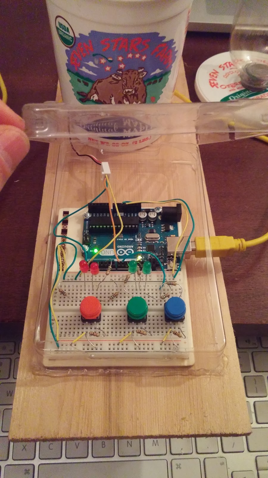
Here is the circuit I built with the three buttons and the speaker.
With its housing on my completed instrument kind of looks like a little piano!
Here's my code
Following Crawford's model of interaction:
Human:
Listen - Observes buttons
Think - Decides to play a song
Speak - Presses buttons
Input - Hears tone
Processing - Decides to stop playing song
Output - Stops pressing button
Result - Tone stops
Computer:
Input - Button press
Processing - Completed circuit!
Determines which button is pressed
Sets the Val of the button to HIGH
If button 1, 2, or 3 the notes 260, 290, or 320 respectively get sent to the speaker
Output - Speaker tone
Listen - No button pressed
Think - Open circuit
Output - Not tone